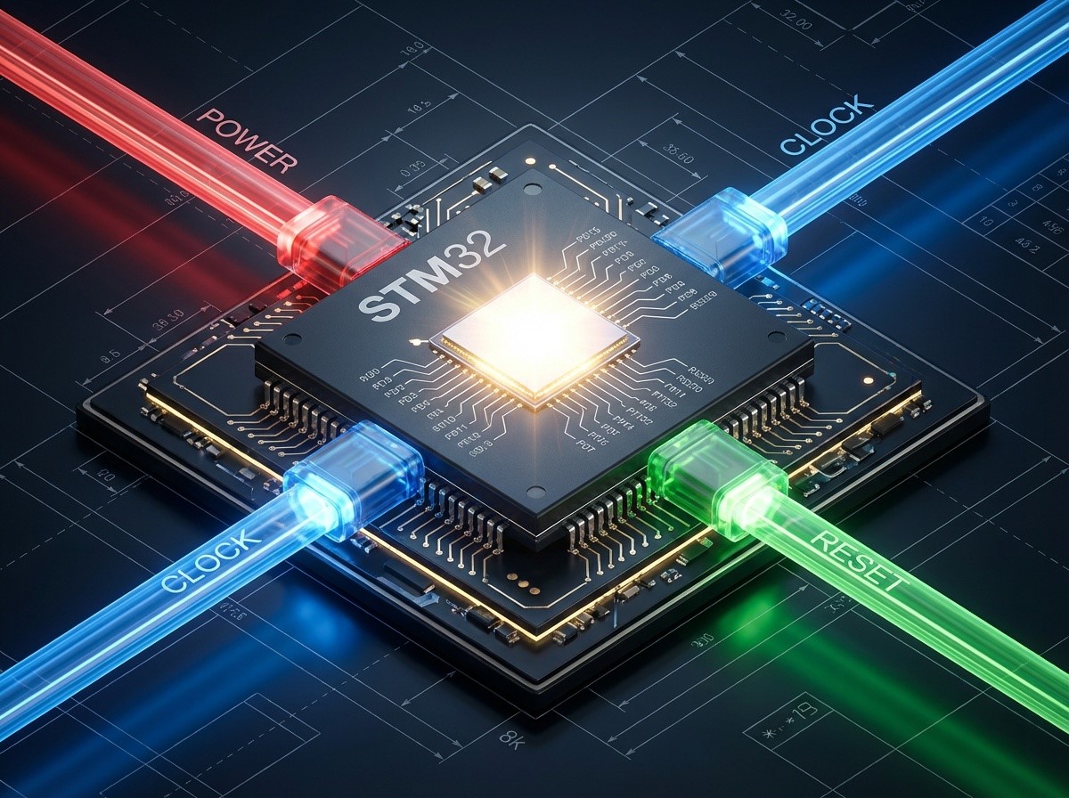
STM32 Minimum System: The Holy Trinity of Hardware (Power, Clock, Reset)
Introduction
Welcome to the hardware fundamentals class! Today, we are discussing the “survival needs” of an MCU. Think of this as the biological requirements for a human; without them, even the most brilliant code won’t make the chip function.
As a technical writer for 123Microcontroller, I’ve distilled complex datasheets into the three core pillars required to wake up an STM32:
- Power Supply: The blood and food (Energy).
- Oscillator: The heartbeat (Timing).
- Reset: The wake-up call (Initialization).
Difficulty: ⭐ Beginner Read Time: ~15 Minutes
1. Power Supply: The Energy Source
The STM32F4 series typically requires a main voltage ($V_{DD}$) range of 1.8V to 3.6V, with 3.3V being the standard for most development boards.
The Secret of “C” (Decoupling Capacitors)
If you look at any schematic or a Discovery board, you will see tiny capacitors placed very close to every power pin.
- The Rule: You must place a 100nF (0.1µF) capacitor near every $V_{DD}$ pin, plus a single bulk capacitor of 4.7µF (or 10µF) for the main line.
- The Function: Think of these capacitors as “personal water bottles” placed right next to the CPU. When the CPU switches states (0 to 1) rapidly, it demands a sudden surge of energy. It drinks from this bottle instantly. If it had to wait for power to travel from the main source (the water cooler down the hall), it would be too slow, causing voltage drops and noise.
VCAP (Internal Core Voltage)
Inside the STM32, a voltage regulator steps down 3.3V to approximately 1.2V to power the Cortex-M4 core.
- Requirement: Connect a 2.2µF (or 4.7µF depending on the specific model) capacitor to the $V_{CAP}$ pin connected to Ground.
- Warning: ⚠️ Never connect an external power source to this pin!
2. Oscillators: The Heartbeat
The microcontroller marches to the beat of its clock. Faster clocks mean faster calculations but higher power consumption.
2.1 HSI (High Speed Internal)
- What is it? An RC Oscillator built directly into the silicon (usually 16 MHz).
- Pros: It’s free! No external components needed. The chip boots up using this by default.
- Cons: Less accurate (~1% error). Not suitable for high-speed UART or USB applications where precise timing is critical.
2.2 HSE (High Speed External)
- What is it? An external Crystal or Ceramic Resonator connected to
OSC_INandOSC_OUTpins. - Range: Typically 4 to 26 MHz (8 MHz is common on Discovery boards).
- Pros: High precision. Mandatory for communication protocols.
PLL (Phase Locked Loop): Think of this as the “Turbocharger.” It takes the 8MHz signal (from HSI or HSE) and multiplies it to reach high speeds like 168 MHz for the STM32F4.
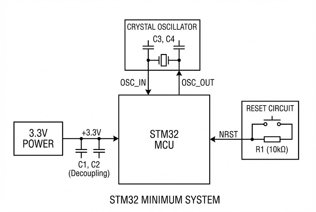
3. Reset Circuit: The Wake-Up Button
The Reset pin on STM32 is labeled NRST. It operates as Active Low (Logic 0 = Reset, Logic 1 = Run).
The Circuit Components:
- Capacitor (100nF): Connected between NRST and Ground. This filters out noise to prevent random resets.
- Push Button: Connected to Ground. When pressed, it pulls NRST to 0V, resetting the chip.
- Pull-up Resistor: The STM32 has an internal weak pull-up, but adding an external 10kΩ resistor to 3.3V is a good practice for reliability.
Bonus: Boot Configuration
Once the chip wakes up, where does it look for code? It checks the BOOT0 and BOOT1 pins.
- BOOT0 = 0 (Ground): Boot from Flash Memory. This is the standard mode for running your uploaded program.
- BOOT0 = 1 (3.3V): Boot from System Memory. This activates the built-in Bootloader (for programming via UART/USB).
Summary Checklist
Planning to design your own PCB? Don’t forget this checklist:
- ✅ Provide 3.3V to all VDD pins and connect all Grounds.
- ✅ Place 100nF capacitors near every power pin + one 4.7µF bulk cap.
- ✅ Connect a 2.2µF cap to the VCAP pin (Core logic power).
- ✅ Pull BOOT0 to Ground (via 10k resistor) for normal operation.
- ✅ Add an 8MHz Crystal if you need precise timing.
With these “vital organs” in place, your STM32 is ready to come to life!