STM32 GPIO Basics: Blinking LEDs & Button Input (The Hardware 'Hello World')

Introduction: The “Hello World” of Hardware
Welcome to your first step into the world of Embedded Systems! As an instructor at 123Microcontroller, I can tell you that making an LED blink is as sacred to hardware engineers as printing “Hello World” is to software developers.
It’s not just about a flashing light; it’s the ultimate confirmation that:
- Your Toolchain is installed correctly.
- You can successfully Flash the chip.
- The chip’s Clock (heartbeat) is beating.
Let’s get started!
Level: ⭐ Beginner Time: ~20-30 Minutes
1. Hardware Mapping
GPIO (General Purpose Input/Output) acts as the “arms and legs” of the microcontroller. On the STM32F4 Discovery board, we have built-in peripherals ready to use without external wiring.
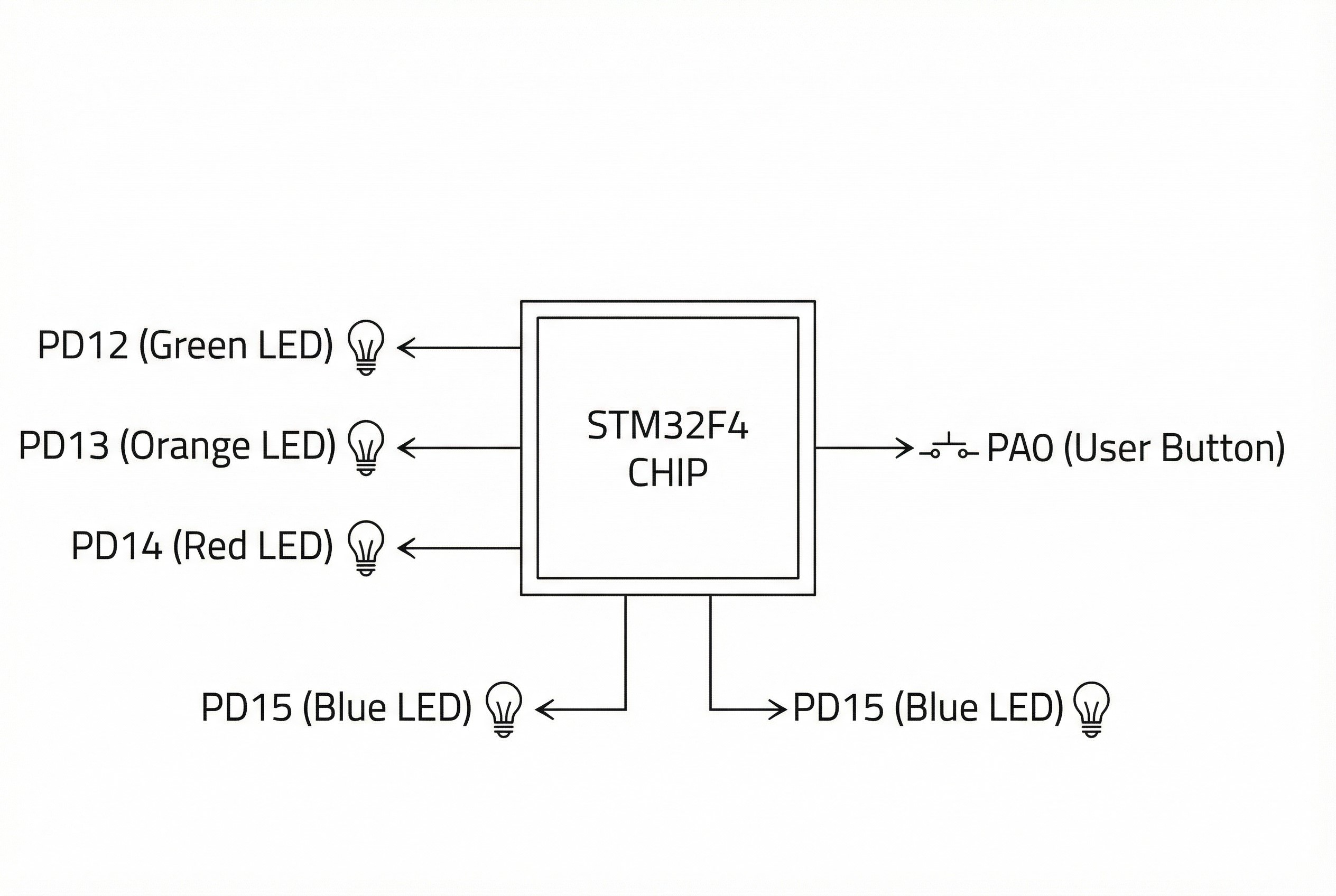
- LEDs (Output):
- 🟢 Green: PD12
- 🟠 Orange: PD13
- 🔴 Red: PD14
- 🔵 Blue: PD15
- Button (Input):
- 🔵 User Button: PA0 (Press = High/1, Release = Low/0)
2. STM32CubeMX Configuration
Open your .ioc file in STM32CubeIDE and follow these steps:
- Enable LEDs (Output):
- Locate pins PD12, PD13, PD14, PD15 on the chip view.
- Left-click and select GPIO_Output.
- Pro Tip: Right-click each pin, select Enter User Label, and name them
LED_Green,LED_Orange, etc. This makes your code much more readable.
- Enable Button (Input):
- Locate PA0 and select GPIO_Input.
- Deep Dive Configuration (System Core > GPIO):
- For LEDs (PD12-15): Set
GPIO Output Levelto Low (start off) andGPIO Modeto Output Push Pull. No Pull-up/Pull-down is needed (the board has external resistors). - For Button (PA0): Set
GPIO Pull-up/Pull-downto No pull-up and no pull-down (the board has an external pull-down resistor).
- For LEDs (PD12-15): Set
- Generate Code: Press
Ctrl+Sto save and generate the initialization code.
3. Code Walkthrough
Open main.c and scroll down to the while(1) loop. We will write our logic inside the USER CODE BEGIN 3 section to ensure it persists if we regenerate the project.
Challenge 1: The Blinky
We use HAL_GPIO_TogglePin to flip the state and HAL_Delay to pause.
  /* USER CODE BEGIN WHILE */
  while (1)
  {
    /* USER CODE END WHILE */

    /* USER CODE BEGIN 3 */
    // Toggle Green LED (PD12) every 500ms
    HAL_GPIO_TogglePin(GPIOD, GPIO_PIN_12);

    // Blocking delay for 500 milliseconds
    HAL_Delay(500);
  }
  /* USER CODE END 3 */
Challenge 2: Button Control
We use HAL_GPIO_ReadPin to check the button status and HAL_GPIO_WritePin to control the LED.
  /* USER CODE BEGIN 3 */
  // Read User Button at PA0
  // If Pressed (State is SET or 1)
  if (HAL_GPIO_ReadPin(GPIOA, GPIO_PIN_0) == GPIO_PIN_SET)
  {
      // Turn ON Orange LED (Write Pin SET)
      HAL_GPIO_WritePin(GPIOD, GPIO_PIN_13, GPIO_PIN_SET);
  }
  else
  {
      // Turn OFF Orange LED (Write Pin RESET)
      HAL_GPIO_WritePin(GPIOD, GPIO_PIN_13, GPIO_PIN_RESET);
  }

  HAL_Delay(10); // Simple Debounce
  /* USER CODE END 3 */
4. Pro Tips for Engineers
Why Push-Pull?
- Push-Pull: Like a water tap with a pump. It can forcefully push current out (High) or drain it to ground (Low). Ideal for driving LEDs.
- Open-Drain: Like a switch connected to the ground. It can only pull to ground or float. Used for protocols like I2C.
The “Atomic” Secret (BSRR Register)
Did you notice that HAL_GPIO_WritePin doesn’t just write to the Output Data Register (ODR)? It writes to the BSRR (Bit Set/Reset Register).
This allows the MCU to change the state of one specific pin without affecting the others and without being interrupted by other processes. This Atomic Operation is crucial for robust real-time systems.
Clock is Key
If you were writing raw register code, you’d need to manually enable the GPIO Clock (e.g., RCC->AHB1ENR). Luckily, HAL’s MX_GPIO_Init() handles this for us (__HAL_RCC_GPIOD_CLK_ENABLE()). Without the clock, the GPIO is technically “dead.”
Homework: Try making the LEDs chase each other in a circle (Green -> Orange -> Red -> Blue). Can you make them spin faster when the button is held down? 🚀