STM32 Boot Process & Vector Table: What Happens Before main()?
STM32 Boot Process & Vector Table: The Hidden Prologue
If main() is the opening scene of your embedded movie, the Boot Process is the entire pre-production phase. Many developers assume that once the chip is reset, it jumps straight to their code. In reality, the ARM Cortex-M architecture performs a specific “sacred ritual” to wake up.
Based on insights from Mastering STM32 and bare-metal programming principles, let’s decode the mechanism that breathes life into your microcontroller.
1. The Reset Sequence: The First 4 Bytes
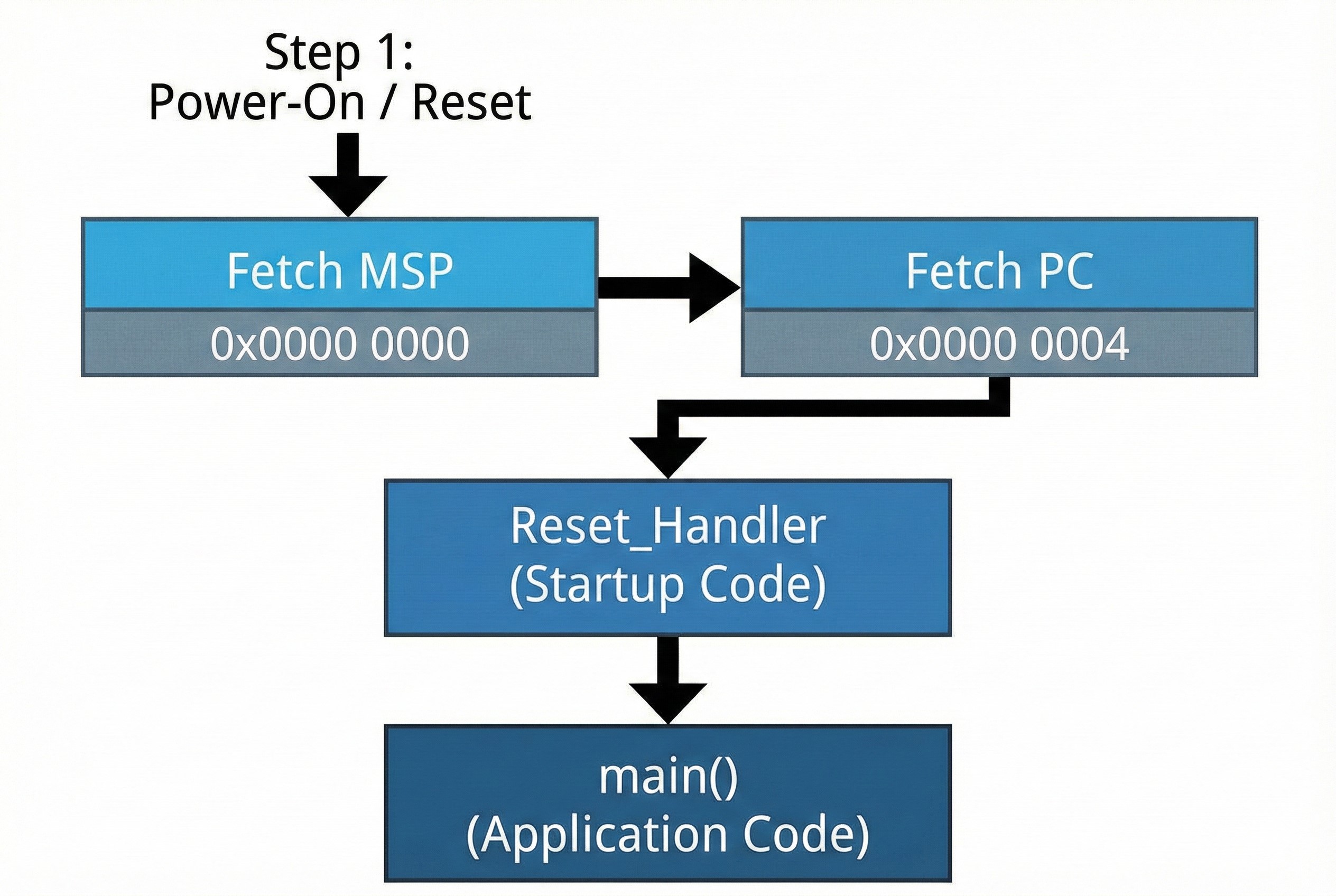
When you power up or reset the board, the CPU doesn’t know where main() is. Instead, the hardware is hardwired to look at the very beginning of the memory map.
- Hardware Fetch (MSP): The CPU reads the first 4 bytes at address
0x0000 0000. It loads this value into the MSP (Main Stack Pointer) to set up the stack for operation. - Fetch Reset Vector: Next, it reads the address at
0x0000 0004. This value is the address of the Reset_Handler. - Jump: The CPU loads this address into the Program Counter (PC) and jumps to the
Reset_Handler.
Architect’s Note: This is why the Vector Table must always be located at the zero address (or mapped there) during startup.
2. Boot Modes: The Art of Memory Aliasing
You might ask: “Wait, STM32 Flash starts at 0x0800 0000. How does the CPU read 0x0000 0000?”
The answer is Memory Aliasing. Depending on the state of the BOOT0 and BOOT1 pins, the STM32 hardware “mirrors” a specific memory region to the zero address:
- Main Flash Memory: Maps
0x0800 0000to0x0000 0000. This is the standard boot mode for running your application. - System Memory: Maps the internal ROM (Bootloader) to zero. Used for flashing via UART/USB DFU.
- SRAM: Maps the RAM to zero. Used for fast debugging without wearing out flash memory.
3. The Vector Table Structure
The Vector Table is essentially an array of function pointers. It tells the CPU where to go when specific events (Exceptions or Interrupts) occur.
| Offset | Function | Description |
|---|---|---|
| 0x00 | Initial SP | The starting address of the Stack. |
| 0x04 | Reset | The entry point of the program (Reset_Handler). |
| 0x08 | NMI | Non-Maskable Interrupt (Critical errors). |
| 0x0C | HardFault | Called when the code crashes (e.g., illegal memory access). |
| 0x40+ | IRQs | Peripherals (Timer, UART, ADC, etc.). |
4. The Reset Handler: The Housekeeper
Before main() runs, the Reset_Handler (usually found in startup_stm32xxxx.s) must prepare the environment:
- Copy .data: Moves initialized variables (e.g.,
int a = 5;) from Flash to RAM. - Zero .bss: Clears uninitialized variables (e.g.,
int b;) in RAM to zero. - SystemInit: Sets up the basic clock system.
- Call main(): Finally, it hands over control to your application.
5. Advanced: Vector Table Relocation (VTOR)
For advanced scenarios like Custom Bootloaders or RTOS, you often need to move the Vector Table.
- Cortex-M3/M4/M7: These cores have a register called
SCB->VTOR. You can simply write the new address (e.g.,0x0800 4000) into this register, and the CPU will look there for interrupts. - Cortex-M0 (STM32F0): These older cores do not have VTOR. To relocate vectors, you must manually copy the table to the start of SRAM and use hardware remapping commands to map SRAM to
0x0000 0000.
Summary
Understanding the boot process distinguishes a hobbyist from a professional engineer. If your board fails to boot, check your BOOT pins. If your variables contain garbage data, check your Linker Script and Startup Code.
Mastering these low-level details gives you full control over the system, especially when building robust industrial applications.